

Air handlers and fans: what to measure, and where it goes.
Coil and filter pressure, fan condition and power, UV-C output, airflow and water at the pan: the readings that show how an air handler is doing between service visits.
Air handler (AHU)
Cooling coilCoil air-side pressure drop
Sound familiar? “We clean the coils every spring whether they need it or not.”
| Sensor | |
|---|---|
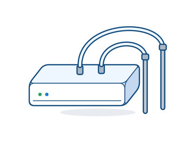
| Where it goes | High-side tube in the gap between the filter bank and the coil’s entering face; low-side tube between the coil’s leaving face and the fan inlet. Sensor body outside the casing, above both ports, so condensate in the tubing drains back into the unit. |
| How it mounts | Tubes through the casing in sealed, grommeted bulkhead fittings. Keep the tubing short, with no sags on the wet (downstream) side. |
| How many | One per coil, or one per coil bank where coils are stacked |
| What it reads | Differential pressure (Pa or in. w.c.); the node also reports temperature and humidity |
| What it catches | Coil fouling and biofilm, blocked fins, a wet coil carrying water |
| What you get | Shows when coil resistance climbs, and whether treatment holds it down, on a time-stamped record |
| Pairs with |
Filter bankFilter pressure drop
Sound familiar? “We swap filters every month, dirty or not.”
| Sensor | |
|---|---|
| Where it goes | A tube on each side of the filter bank; pre-filters and final filters measured separately. Sensor body outside the casing. |
| How it mounts | Bulkhead fittings through the casing; short tubing. |
| How many | One per filter stage |
| What it reads | Differential pressure (Pa or in. w.c.) |
| What it catches | Loaded filters, filter bypass, a missing or collapsed filter |
| What you get | Filters changed when they load instead of by the calendar |
| Pairs with |
Supply-fan motorFan motor current and energy
Sound familiar? “The utility wants proof of the savings before it pays the rebate.”
| Sensors | |
|---|---|
| Where it goes | Clamp one phase conductor of the fan motor feeder at the disconnect or starter. With a variable-frequency drive, clamp on the line (input) side. |
| How it mounts | Split-core, so no shutdown is needed; an electrician opens the enclosure under the site’s energized-work rules. Self-powered clamps draw their power from the load. |
| How many | One per fan motor; No. 69 where true kW and power factor are wanted |
| What it reads | True-RMS current (A) and amp-hours; No. 69 adds voltage, power factor and kWh |
| What it catches | Rising fan power from coil and filter loading; a stopped fan or a broken belt |
| What you get | An energy record for the fan before and after treatment |
| Pairs with |
Supply fan and motorVibration and bearing temperature
Sound familiar? “The fan quit Friday night and nobody knew until Monday.”
| Sensor | |
|---|---|
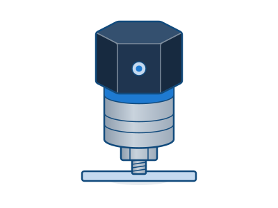
| Where it goes | Motor drive-end and non-drive-end bearings, and the fan shaft’s pillow-block bearings on the rigid bearing cap. Axial reading at the thrust bearing. Never on the fan shroud, belt guard or thin sheet metal. |
| How it mounts | Stud mount is best; an epoxy pad where drilling isn’t allowed; a flat magnet on flat, bare steel only. Clean to bare metal and mark the axes. Install with the machine locked out unless the magnet can go on from outside the guard. |
| How many | One per machine to start. Large or critical machines can take one at each main bearing; an engineer sets the count at the assessment. |
| What it reads | Vibration velocity (mm/s), acceleration and peak (g), kurtosis and crest factor; surface temperature (°C) |
| What it catches | Imbalance, misalignment, looseness, bearing wear and lubrication problems; belt wear and slip |
| What you get | Early warning of a developing fault, so the repair is planned for downtime instead of forced by a stop |
| Pairs with |
UV-C lamp arrayUV-C output at 254 nm
Sound familiar? “Honestly, we don’t know if those UV lamps are still on.”
| Sensor | |
|---|---|
| Where it goes | Sensor head facing the lamp array inside the irradiated zone at the coil face, at a fixed distance and angle so the reading repeats; clear of lamp brackets and condensate drip. |
| How it mounts | Fixed bracket; the distance is recorded at commissioning. The sensor sits inside the unit, so access is under the UV-C lockout and the door switch. |
| How many | One per lamp array; an engineer may add a second at a large coil |
| What it reads | UV-C irradiance at 254 nm (mW/cm²) |
| What it catches | Lamp failure, output falling with age, a ballast fault, lamps switched off |
| What you get | A live reading of lamp output, and lamp changes on condition instead of the calendar |
| Pairs with |
Supply ductSupply airflow
Sound familiar? “The rooms at the end of the duct are always stuffy.”
| Sensor | |
|---|---|
| Where it goes | In the supply duct on the longest straight run available, away from elbows, dampers, coils and the fan discharge, with the probe tip at a representative point in the cross-section. |
| How it mounts | One drilled hole. Longer probe versions suit larger ducts. |
| How many | One per air handler |
| What it reads | Air velocity (m/s); flow estimated from the duct area |
| What it catches | Lost airflow from filter or coil loading, belt slip or a closed damper |
| What you get | Separates “the fan works harder” from “less air reaches the space” |
| Pairs with |
Leaving airSupply-air temperature and humidity
Sound familiar? “It’s cold in here, but it feels damp.”
| Sensor | |
|---|---|
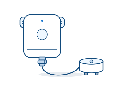
| Where it goes | Probe in the leaving air after the coil; the node outside the casing on its 2 m cable. |
| How it mounts | Probe through a grommet; node on the casing or a wall. |
| How many | One per air handler |
| What it reads | Temperature (°C) and relative humidity (%) |
| What it catches | A coil that isn’t dehumidifying; moisture carried past the coil |
| What you get | Shows the coil’s dehumidification over time, beside its pressure drop |
| Pairs with |
Drain panWater at the drain pan
Sound familiar? “The first we heard of it was a stain on the ceiling tile.”
| Sensors | |
|---|---|
| Where it goes | Probe on the unit floor or the floor below, at the lowest point beside the pan and below the overflow lip, or in the secondary pan. |
| How it mounts | The probe sits on the surface; the node or lead stays outside the wet area. |
| How many | One per drain pan |
| What it reads | Water present or absent |
| What it catches | A blocked condensate drain, pan overflow, wet insulation |
| What you get | Catches an overflow before it reaches a ceiling, floor or switchgear |
| Pairs with |
Access doorDoor opened
Sound familiar? “Did the contractor actually change the filters, or just sign the sheet?”
| Sensor | |
|---|---|
| Where it goes | Magnet on the door and contact on the frame, latch side, near the UV-C or filter section. |
| How it mounts | Screw or adhesive. |
| How many | One per service door that matters |
| What it reads | Open, closed and tamper events |
| What it catches | Unrecorded service visits; a door left open |
| What you get | A record that maintenance opened the unit, beside the filter and lamp readings |
| Pairs with |
PTAC (guest room or dorm)
Unit run current, sampled
Sound familiar? “The PTACs run all day in rooms nobody’s in.”
| Sensor | |
|---|---|
| Where it goes | A 100 A clamp on the PTAC’s branch circuit in the panel, on a sample of units rather than every one. |
| How it mounts | Split-core in the panel; an electrician installs. |
| How many | A sample of units across the building; an engineer sets the share at the assessment |
| What it reads | Current (A) and amp-hours |
| What it catches | Units running when rooms are empty; a failing compressor |
| What you get | Run hours and energy for the PTAC fleet from a sample of rooms |
CRAH or CRAC (data hall)
Fan vibration, filter pressure drop and rack inlet temperature
Sound familiar? “We find the hot spots when a server starts alarming.”
| Sensors | |
|---|---|
| Where it goes | Vibration on each CRAH fan motor bearing; filter pressure drop across the CRAH filters; temperature and humidity at rack inlets on the cold aisle, at the top, middle and bottom of selected racks. |
| How it mounts | Magnet or stud for vibration; adhesive for the rack sensors. |
| How many | One vibration sensor per CRAH fan and one pressure sensor per CRAH; rack inlet points set per aisle at the assessment |
| What it reads | Vibration; differential pressure; inlet temperature and humidity |
| What it catches | CRAH fan faults, loaded filters, hot spots at rack inlets |
| What you get | Uptime evidence on a data path that stays off your network, through a cellular gateway |
| Pairs with |
Exhaust fan (roof or wall)
Vibration
Sound familiar? “Thirty fans on the roof, and we only find the dead ones on rounds.”
| Sensor | |
|---|---|
| Where it goes | Motor drive-end bearing, and the fan shaft bearings on belt-driven units; never on the fan housing or shroud. |
| How it mounts | Stud mount is best; an epoxy pad where drilling isn’t allowed; a flat magnet on flat, bare steel only. Clean to bare metal and mark the axes. Install with the machine locked out unless the magnet can go on from outside the guard. |
| How many | One per fan to start; a critical fan can take one at each bearing |
| What it reads | Vibration velocity (mm/s), acceleration and peak (g), kurtosis and crest factor; surface temperature (°C) |
| What it catches | Imbalance, misalignment, looseness, bearing wear and lubrication problems |
| What you get | Catches a failing exhaust fan before it stops |
| Pairs with |
Placement and quantities are starting points from Cognituv’s install guidance. A Cognituv engineer confirms them for your site, and the product data sheet governs. Electrical and hazardous-area work follows the site’s own rules and permits.
Have an equipment list?
Upload it in the planner. It suggests what to measure on each asset and a gateway to carry it, and a Cognituv engineer confirms the plan.
Prefer to talk? Call 1-888-580-8738